Build Your Own Wi-Fi RC Car: A Step-by-Step Guide Using ESP8266
Have you ever wanted to build a remote-controlled car that doesn’t rely on expensive Bluetooth modules or bulky controllers? By using the ESP8266 Dev Board, you can create a high-performance RC car controlled entirely through your smartphone via Wi-Fi. In this guide, we’ll walk through the hardware assembly, wiring and software setup to get your car moving.
Components Required
- 1x ESP8266 Dev Board
- 1x L298N Motor Driver Module
- 4x BO Motors
- 4x Wheels (65mm)
- 2x 18650 Li-ion Batteries
- 1x 18650 2-cell Battery Holder
- Cardboard (For the chassis)
- Jumper wires
- Tools: Hot Glue Gun
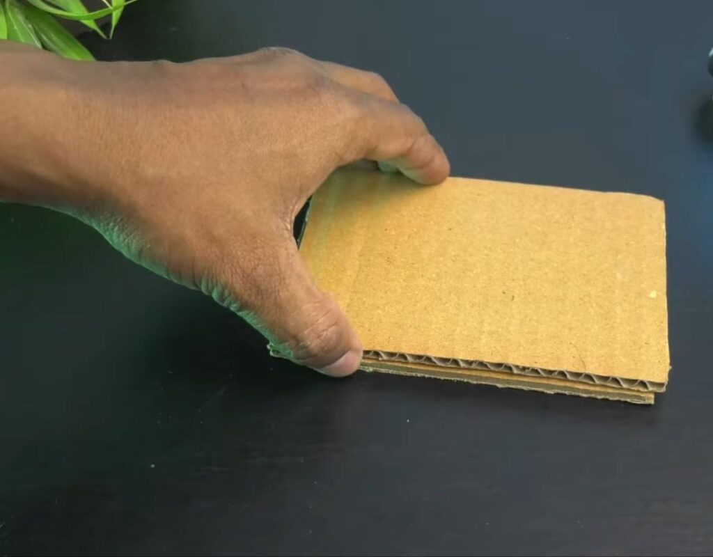
Step 1: Creating the Chassis
- Cut two rectangular pieces of sturdy cardboard of the same size.
- Apply hot glue to one piece and stack the second one on top to create a reinforced, thick base for your car.
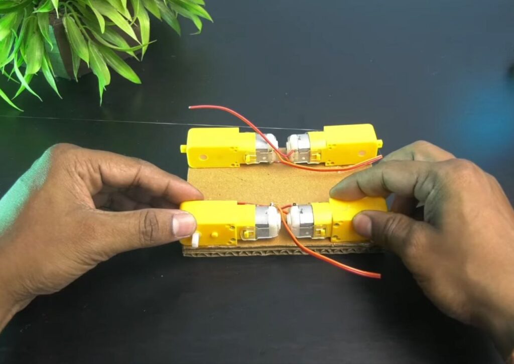
Step 2: Mounting the Motors
- Apply hot glue to the four corners of the bottom of your cardboard chassis and press the BO motors into the glue, ensuring they are aligned straight.
NOTE: Remember that the face of the motor shafts should be outward so that the wheels have plenty of clearance.
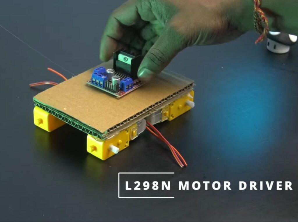
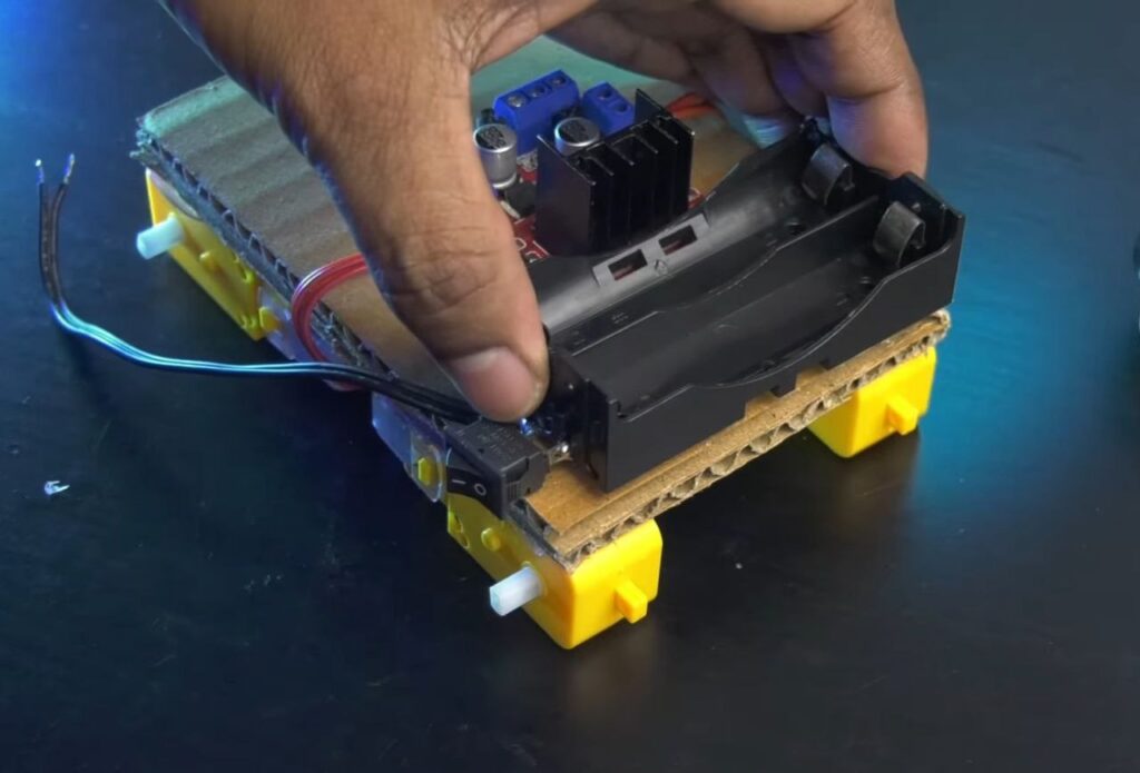
Step 3: Mounting the Electronics
- Flip the chassis over and use hot glue to mount the L298N Motor Driver in the centre and the Battery Holder towards the rear.
Step 4: Wiring the Motor Driver
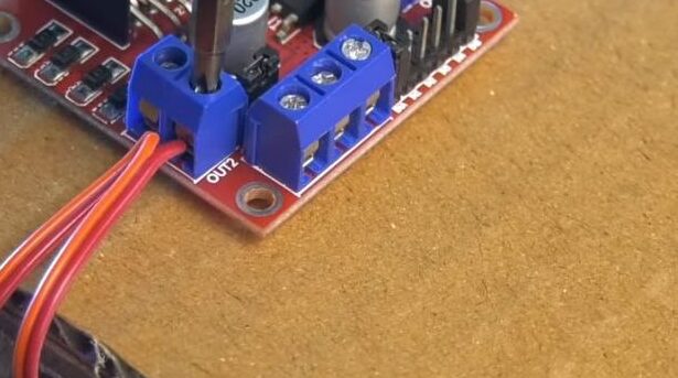
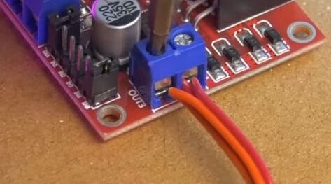
- Motors: Connect the wires from the two motors on the left side to the OUT1 & OUT2 terminals on the L298N. Connect the two right-side motors to OUT3 & OUT4.
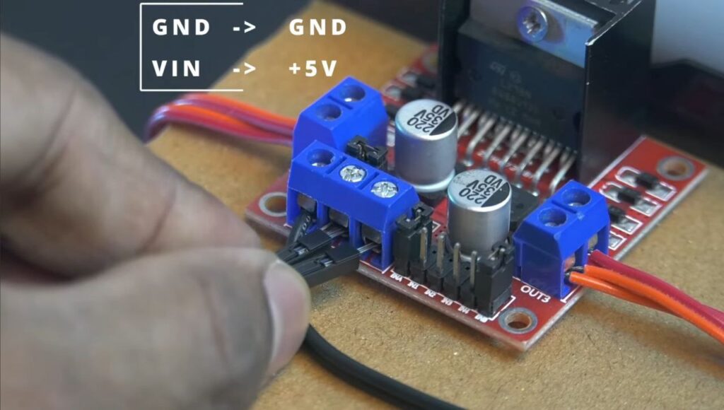
- Power: Connect the positive wire from the battery holder to the 12V terminal on the L298N. Connect the negative wire to the GND terminal.
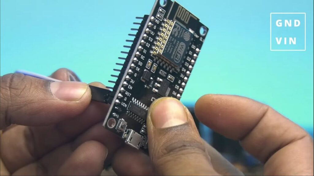
- Powering the ESP 8266: Run a wire from the L298N’s +5V terminal to the VIN pin on the NodeMCU, and connect the GND from the L298N to the GND pin on the NodeMCU.
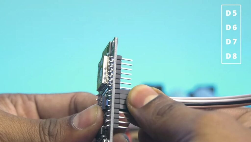
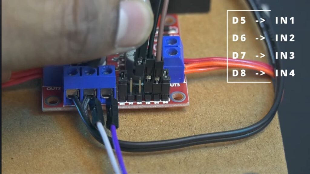
Step 5: Logic Connections (ESP8266 to L298N)
Connect the following pins using jumper wires:
- D5: IN1
- D6: IN2
- D7: IN3
- D8: IN4
After the wiring of ESP 8266 Board is complete, fix the ESP 8266 Dev Board at the front or side where it’s easily accessible for programming.
NOTE: Before mounting the wheels, we have to upload the Code. So, put the battery switch OFF and then connect the ESP 8266 board to the computer via USB.
Step 6: Software Setup
1. Prepare the Arduino IDE:
- Open Arduino IDE on your computer.
- Go to File > Preferences.
- In “Additional Boards Manager URLs,” paste this link and click OK: https://arduino.esp8266.com/stable/package_esp8266com_index.json
- Go to Tools > Board > Boards Manager, search for “esp8266,” and click Install.
2. Uploading the Code
- Connect your NodeMCU to your computer via USB.
- In the IDE, go to Tools > Board and select NodeMCU 1.0 (ESP-12E Module).
- Select the correct Port.
- Upload your code (ensure your code matches the pin definitions: D5, D6, D7, D8).
- Once “Done Uploading” appears, disconnect the USB.
Step 7: Final Testing
- Attach the Wheels: Press the wheels onto the motor shafts.
- Power On: Flip the toggle switch on your battery pack.
- Install the App: Download ESP8266 Wi-Fi Robot Car controller app from the Play Store.
- Connect to Wi-Fi: Open your phone’s Wi-Fi settings and connect to the network created by the ESP 8266 Board.
- Drive: Open the app, use the on-screen arrows and just drive away!.